Design of bolted flange connections for offshore wind foundations - Monopiles
Introduction
The design of flange connections for monopiles - offshore wind foundations
Bolted ring L-flange connections are typically used in the wind industry to connect tower and foundation sections. The flange dimensions are often determined using analytical methods, although this lacks the precision of more refined finite element analyses. The main reason being time constraints in the design process, where the analytical method offers the possibility to quickly evaluate the capacity.
Using yield-line theory for plates several geometrically possible global and local failure modes are investigated. The application of the suggested approach is expected to result in more accurate predictions of the limit load of bolted ring L-flange connections and give more cost-effective flange designs.
Beam Analogy
For designing cylindrical flange connections used for monopiles, jackets etc.
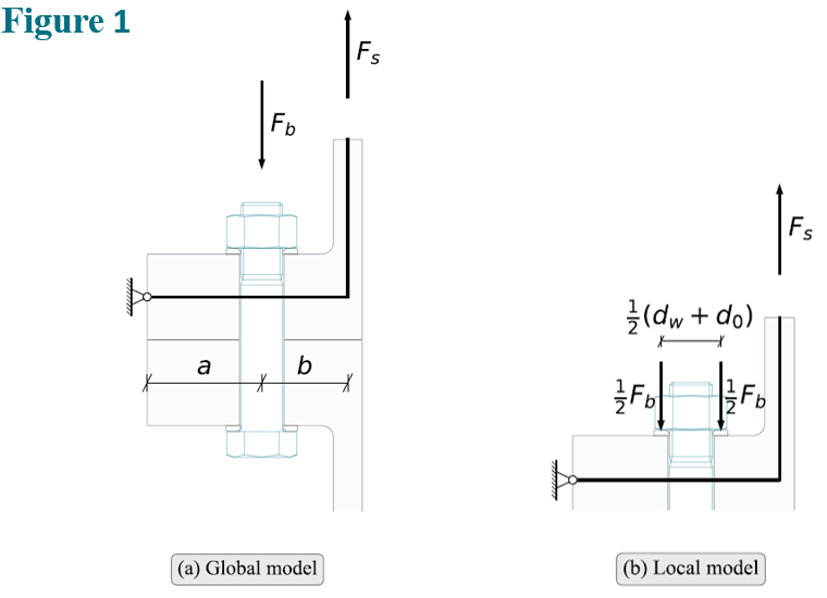
Petersen [1] introduced a beam analogy for the flange and the cylindrical shell, Figure 1, whereby, the limit load could be calculated by considering three mechanisms:
- Failure of the bolts with little or no deformation of the flange.
- Hinge forming near the connection between flange and shell combined with yielding of the bolt
- Hinges forming in the flange at the bolt axis and at the connection between flange and shell.
Schaumann and Seidel [2] later modified this approach, replacing failure mode C with two failure modes:
- Hinges forming in the flange at the bolt axis and at the connection between flange and shell combined with yielding of the bolt.
- Hinges forming in the flange under the bolt washer and at the connection between flange and shell.
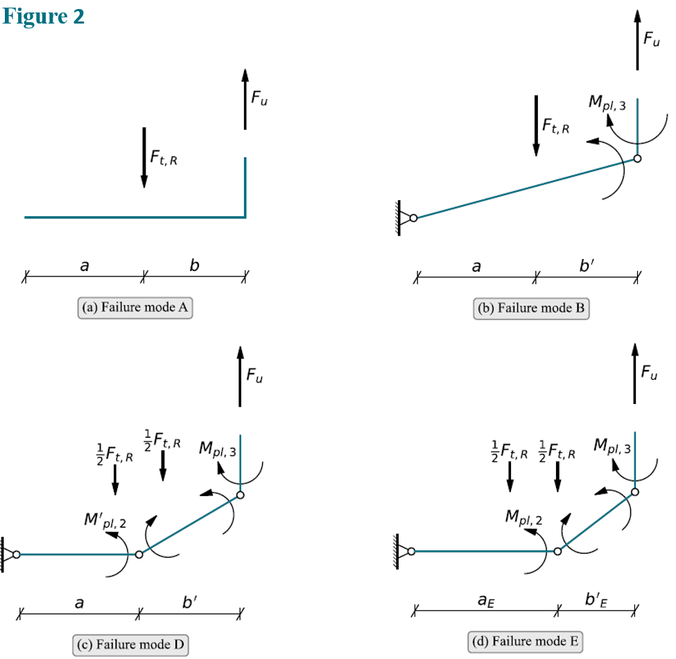
Figure 2 displays the series of considered failure modes using the beam analogy
Yield-line Theory
For evaluation of failure modes in the foundation / tower flange connection
Yield-line theory was pioneered by Johansen, [3] as a method of investigating the capacity of concrete plates by introducing failure mechanisms and considering equilibrium through the work performed.
In the following sections yield-line theory is used to evaluate geometrically possible circular failure modes of the flange connection corresponding to the beam failure modes B, D and E, Figure 2. Additionally, two local failure modes around the bolt holes, F and G, are considered, since they potentially could be more critical than the global modes:
- A circular failure mode developing in the flange connection around the bolts.
- A failure mode consisting of a half-circle combined with straight yield-lines propagating to the flange edge.
Since failure mode A covers the failure of the bolts in tension with little or no deformation of the flange, the capacity will not be affected by considering a plate yield-line mechanism. The limit load can subsequently be calculated as proposed by Petersen [1].
Failure Mode B
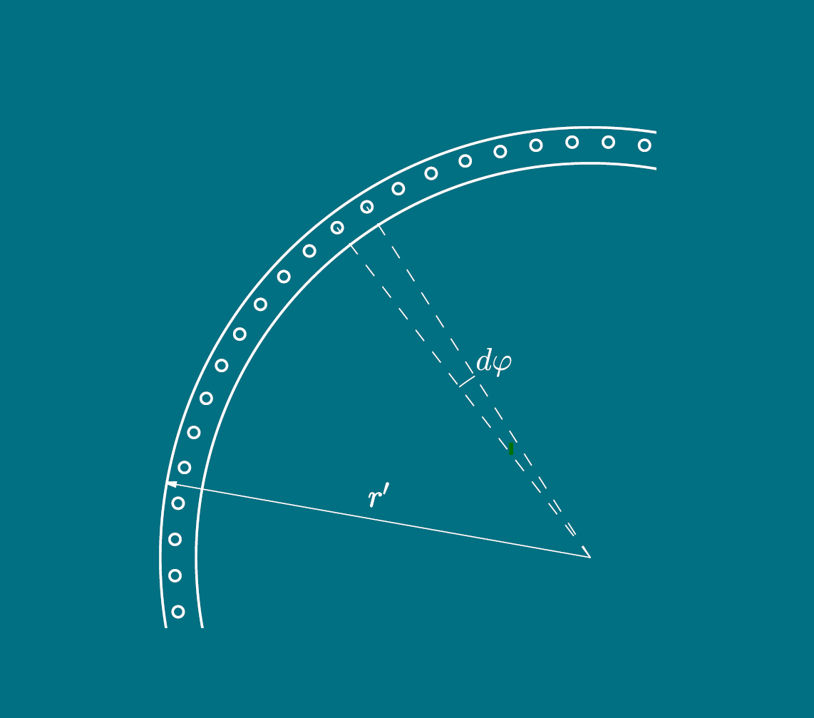
Igarashi et al. [4] and Couchaux et al. [5] derived expressions for the capacity of a plate failure mechanism similar to beam failure mode B, but did not account for the bolt holes. Figure 3 displays the plate failure mechanism considering the bolt holes. Equilibrium requires that the work of the internal forces must be equal to the work of the external forces:

(1)
The internal work performed at the circumferential yield-line is given by:

(2)
At the radial yield-lines the internal work becomes:
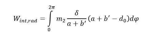
(3)
The external work performed by the bolt forces and the shell force is:

(4)
Substituting (2), (3) and (4) into (1) and solving for Fu:
(5)
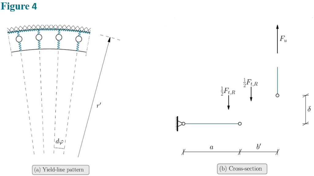
Failure Mode D
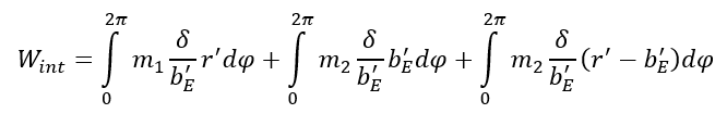
Conservatively it is assumed that the length of the yield-lines will be reduced due to the presence of the bolt holes as illustrated in Figure 4. The internal work can be obtained from:
(6)
Where r´b is the effective bolt circle radius i.e., the radius is reduced due to the presence of the bolt holes:

(7)
The external work is determined assuming that half of the bolt force acts on the washer as shown in Figure 1.

(8)
The ultimate capacity of the connection then becomes:
(9)
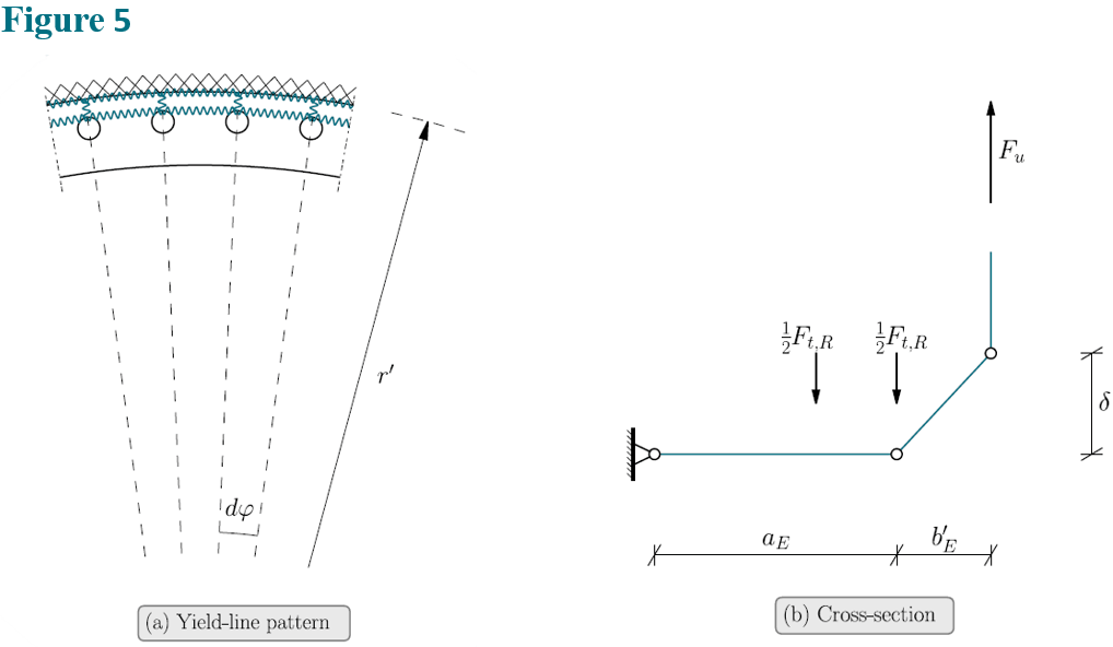
Failure Mode E
Failure mode E constitutes a failure of the flange connection and possibly the shell without yielding of the bolts, Figure 5. Similar failure modes are described by Igarashi et al. [4] and Kato and Hirose [6], in the latter case the failure mode takes the shape of a dodecagon.
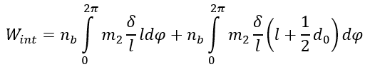
The internal work is obtained from:
(10)
Only the shell force contributes to the external work:

(11)
Considering the internal and external work the ultimate capacity of the flange connection is given by:

(12)
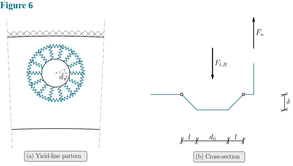
Failure Mode F
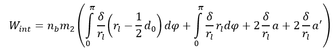
In addition to the global failure modes, local failure modes of the flange connection around the bolts needs to be considered. One such failure mode is the cone shaped mode shown in Figure 6. The internal work associated with the failure mode is:
(13)
The external work is obtained as:

(14)

(15)
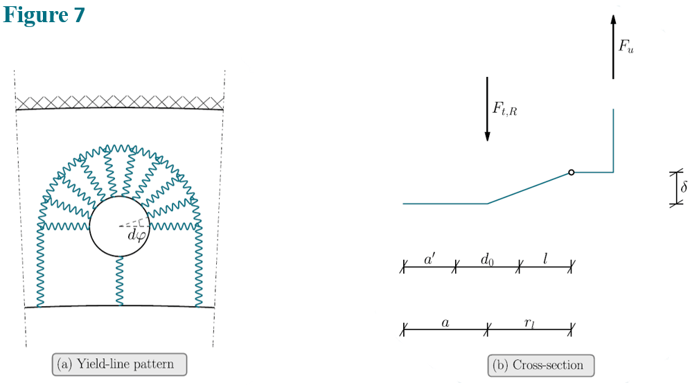
Failure Mode G
Another possible failure mode around the bolts is depicted in Figure 7. If the bolts are placed close to the flange edge, this mode is likely to be associated with a lower ultimate capacity than mode F. The internal work is determined assuming that the flange edge is straight i.e. the length of the yield-lines running from the edge is taken as ![]() :
:
(16)
The external work is determined as:

(17)
Substituting (16) and (17) into (1):

(18)
How is the limit load of bolted flange connections for monopiles calculcated

Using yield-line theory for plates several geometrically possible global and local failure modes can be assessed simply with great accuracy.
How are flanges for offshore foundations designed
Flanges for offshore foundations can be designed analytically and by the means of finite element analysis. Analytically, yield-line theory for plates can be used for a fast yet accurate assessment. Using finite element analysis the assessment time increases with the accuracy.
Disclaimer
Venfluc ApS cannot accept any legal responsibility or liability for any errors or omissions that may be present in this article.
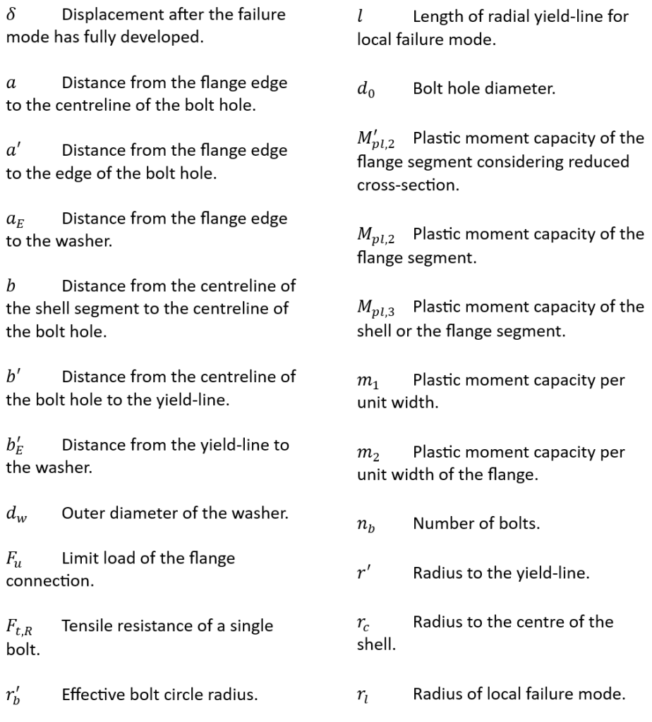
Nomenclature
References
[1] C. Petersen, Stahlbau, Vieweg, Braunschweig, 1997 (in German).
[2] P. Schaumann, M. Seidel, Zur bestimmung der grenztragfähigkeit von verbindungen mit planmäßig auf zug beanspruchten schrauben, Bauingenieur 75 (2000) 637-645 (in German).
[3] K. W. Johansen, Beregning af krydsarmerede jærnbetonpladers brudmoment, Bygningsstatiske Meddelelser BSM 3-1 (1931) 1-18 (in Danish).
[4] S. Igarashi, K. Wakiyama, K. Inoue, T. Matsumoto, Y. Murase, Limit design of high strength bolted tube flange joints, part 1. joint without rib-plates and ring-stiffeners, Journal of structural and construction engineering Transactions of AIJ 354 (1985) 52-66 (in Japanese).
[5] M. Couchaux, M. Hjiaj, I. Ryan, Static resistance of bolted circular flange joints under tensile force (2010) 27-35.
[6] B. Kato, R. Hirose, Bolted tension flanges joining circular hollow section members, Journal of Constructional Steel Research 5 (1985) 79-101.
